


Increasing fluxgate magnetometer sensitivity
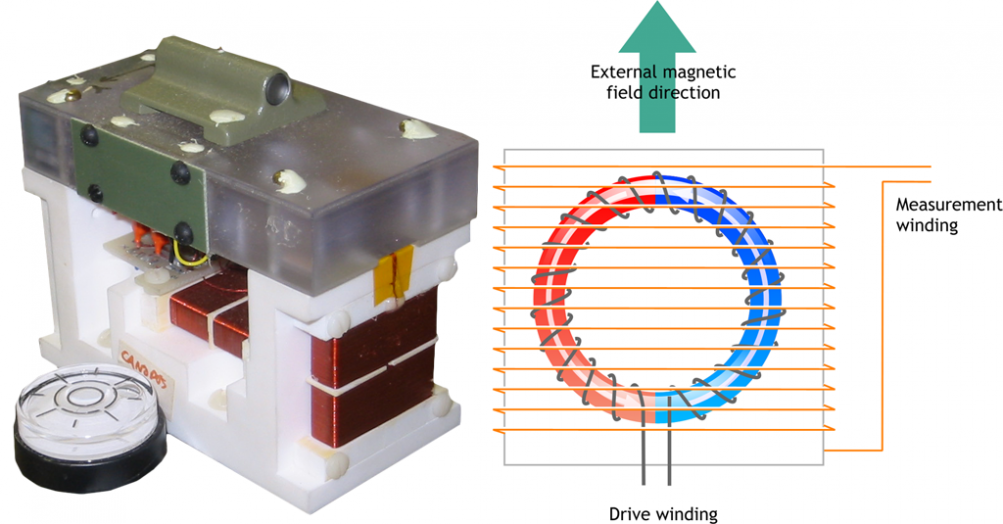
A picture and schematic of the magnetometers used in the CARISMA array can be seen on the right. To increase sensitivity, the core is in the form of a ring, with the drive winding wrapped around it. Wrapped around the outside is a measurement winding.
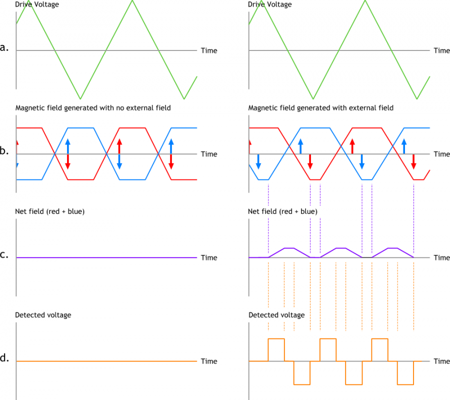
The ring can be thought of as two half rings, working in opposite directions like two rods. With no external field, the field induced by the alternating current in one half of the ring cancels out the other leading to no net field change. However, with an external field present in the direction indicated, the two half rings come to saturation at different times, which causes a changing magnetic field inside the measurement winding, which is picked up as an induced voltage. The magnitude of the voltage and phase relative to the drive frequency can be calibrated to generate information about the magnitude and direction of the external magnetic field.
The CARISMA magnetometers operate in a closed-loops system, where a voltage or current is applied to the sense windings to negate any induced voltage. The applied voltage or current is then a measure of the external field present.
Three coils are mounted in an orthogonal arrangement, providing a vector measurement of the field.
Specifications of CARISMA fluxgate magnetometers
| Dynamic Range: | +/- 80000 nT on all axes |
| Resolution: | 0.025 nT |
| Temperature Coefficient: | < 0.1 nT / ° C |
| Drift: | < 0.01 nT /day |
| Internal instrument noise: | < 0.007 nT @ 1 Hz |
| Axes orthogonal tolerance: | 0.1 degree |
